Home

Επιρροή Με άλλα συγκροτήματα μεταφορά buck boost chopper ψηλός Ποικιλόχρους Θυμίαμα

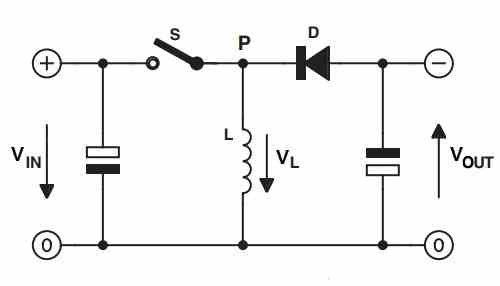
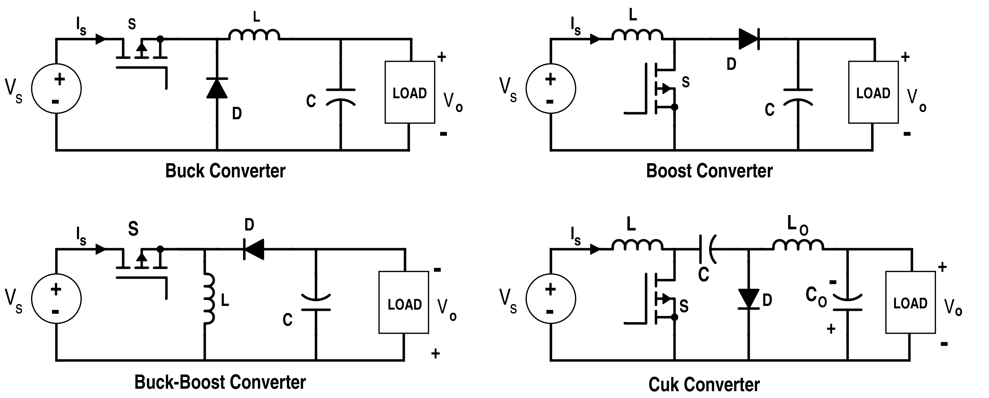
Analysis of Four DC-DC Converters in Equilibrium - Technical Articles

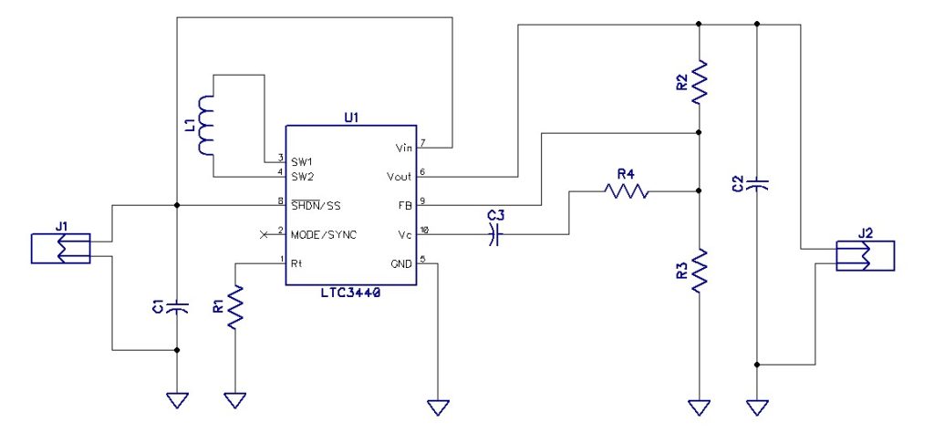
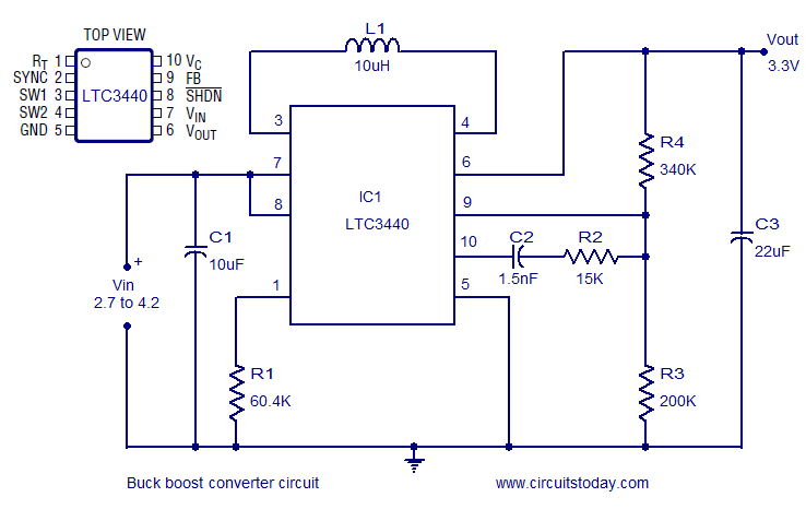
2.7V-4.2V input to 3.3V output Buck-Boost Converter - Electronics-Lab.com

Buck Boost converter using LTC3440 for an output voltage of 3.3 volts.

Buck Boost Converter - MATLAB & Simulink

Texas Instruments' (TI) New Buck-Boost Converter Features 60nA Quiescent  Current - New Industry Products
Texas Instruments' (TI) New Buck-Boost Converter Features 60nA Quiescent Current - New Industry Products

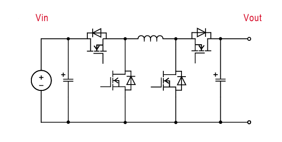
Do not operate a 4 switch buck-boost converter in buck-boost mode - Power  management - Technical articles - TI E2E support forums
Do not operate a 4 switch buck-boost converter in buck-boost mode - Power management - Technical articles - TI E2E support forums

Ridley Engineering | - [020] Buck-Boost Converter with Current-Mode Control

Simple Buck-Boost Converter Circuits Explained | Homemade Circuit Projects

Monolithic Buck-Boost Converter Provides 1A at 3.3V without Schottky Diodes  | Analog Devices
Monolithic Buck-Boost Converter Provides 1A at 3.3V without Schottky Diodes | Analog Devices

Basic buck-boost converter circuit with rectifiers [5]. | Download  Scientific Diagram
Basic buck-boost converter circuit with rectifiers [5]. | Download Scientific Diagram

The Buck boost regulator shown in figure has an input voltage of Vs=12V.  The duty cycle is 0.25 and the switching frequency is 25 kHz. The  inductance L =150 μ H and
The Buck boost regulator shown in figure has an input voltage of Vs=12V. The duty cycle is 0.25 and the switching frequency is 25 kHz. The inductance L =150 μ H and

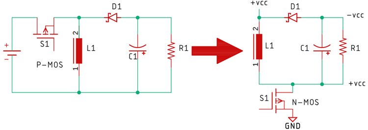
High Power Inverting Buck-Boost Converter Circuit Design with TL494 IC

Buck–boost converter - Wikipedia

Buck-Boost, Buck Converters - STMicroelectronics

Buck Boost Converter, working, principle and waveform [Hindi] - YouTube

Electronics | Free Full-Text | Dynamic Analysis of the Switched-Inductor  Buck-Boost Converter Based on the Memristor
Electronics | Free Full-Text | Dynamic Analysis of the Switched-Inductor Buck-Boost Converter Based on the Memristor

Does the buck_boost dc_dc converter produce a positive or negative voltage?  - Quora
Does the buck_boost dc_dc converter produce a positive or negative voltage? - Quora

Solved Buck-Boost Converter • 3.10bjective • The objective | Chegg.com

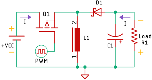
Buck-Boost Converter: What is it? (Formula and Circuit Diagram) |  Electrical4U
Buck-Boost Converter: What is it? (Formula and Circuit Diagram) | Electrical4U

Buck–boost converter - Wikipedia

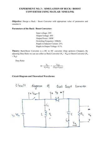
Buck Boost Converter with simulation model.pdf

dcdc_bidir_bck_bst_050v

Mains Buck Boost Chopper Trainer ST BBC-01, For Laboratory, Packaging Type:  Box
Mains Buck Boost Chopper Trainer ST BBC-01, For Laboratory, Packaging Type: Box

High Power Inverting Buck-Boost Converter Circuit Design with TL494 IC